
Particle Insertion and Removal
Configuration of inlets and outlets that feed or remove material from the domain.
11.1 Insertion panel
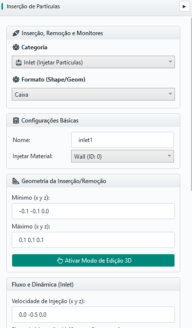
The module Insertion configures three types of entity, defined by Category: inlets (inject particles in the domain at configurable rate and speed), outlets (remove particles passing through an exit surface), and region monitors (measure particles crossing a surface, without removing them — Chapter 16.8). The Format available depends on the chosen category (11.3).
11.2 Category and name
Choose Inlet to feed material or Outlet to remove material. Each item must have a clear name, especially when the case has multiple entry/output points (e.g.: inlet_alimentador_principal, outlet_descarga_silo).
11.3 Insertion geometry
| CATEGORY | AVAILABLE SHAPES | NOTE |
|---|---|---|
| Inlet | Box, Disc, Cylinder, Cone/truncated cone | "Point" only appears when editing an older project that already uses it — no longer offered for new inlets; prefer Disc |
| Outlet | Infinite plane, Box | No Disc/Cylinder/Cone — a simple exit surface is enough to capture removal |
| Region monitor | Infinite plane, Box | Same shapes as Outlet, but measures without removing (Chapter 16.8) |
Depending on the Format selected, the displayed fields change (Box uses min/max in x, y, z; Disc uses center, normal and radius; Cylinder uses two axis points and a radius; Cone/truncated cone uses two axis points and the two radii; Infinite plane uses a point and a normal). The button Enable 3D Edit Mode allows dragging the region directly into the viewport; after the visual editing, review the numerical values.
11.4 Speed and flow
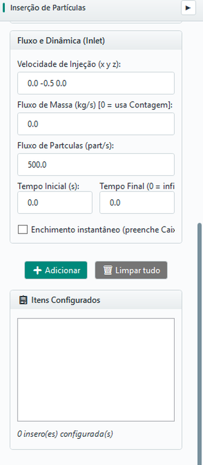
The inlet’s dynamic parameters appear in the expander Flow and Dynamics (Inlet):
| FIELD | UNIT | MEANING |
|---|---|---|
| Injection speed | m/s | V0 particle vector at the time of creation |
| Mass flow | kg/s | Desired mass rate (0 = use count) |
| Particle flow | part/s | Rate per count (used when mass flow = 0) |
| Start time / end time | s | When the inlet starts operating and when it shuts down (0 = infinite) |
If the mass flow is zero, the system uses the particle flow to determine the creation rate. At least one of the two must be defined.
11.5 Instant filling and overlap prevention
Option Instant filling (fill box) fills the insertion region with particles at the initial moment, instead of injecting them by rate. In this mode, the flow field becomes number of particles. Instant filling prevents the creation of particles that would overlap walls/STL in the region (avoiding "explosion" at the beginning) - prevention that the injection by rate does not.
11.6 Particle size distribution (PSD)
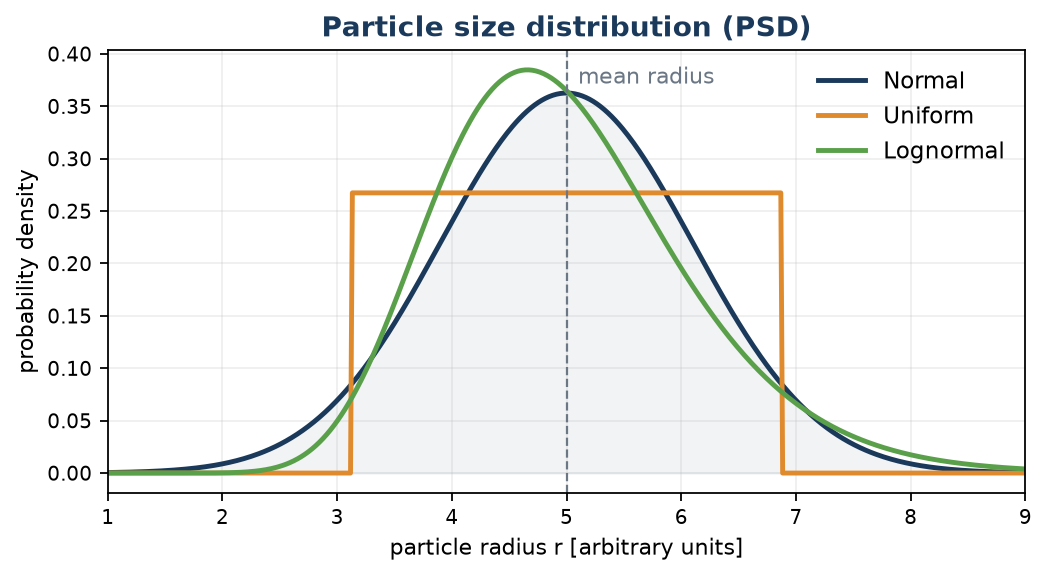
Instead of all particles of the same radius (monodisperse), the inlet can draw the radius of each particle from a size distribution (PSD). This better represents real materials, which have a range of sizes, and is essential to study segregation and screening. BrixDEM offers three distributions:
| DISTRIBUTION | BEHAVIOR | WHEN TO USE |
|---|---|---|
| Normal (Gaussian) | Radii around the mean with standard deviation; symmetrical | Homogeneous material with moderate dispersion of size |
| Uniform | All radii within the range are equally likely | Known particle size range without preferential size |
| Lognormal | Asymmetrical, with tail for larger sizes | Powders and crushed materials (very common in real granular materials) |
The parameters of PSD are:
| PARAMETER | MEANING |
|---|---|
| Mean radius | Central distribution size (average for Normal/LogNormal; center for Uniform) |
| Standard deviation | Distribution spread (half-width for Uniform) |
| Minimum/maximum radius | Truncation Limits - No particle is generated outside this range |
11.7 Mixture of materials in inlet
A single inlet can inject more than one material with defined weights - e.g. 70 % sand and 30 % pellets. This creates a mixture or bidisperse system at the source ideal for studying mixing and segregation (The Lacey mixing index is calculated automatically when there are two or more species - see Chapter 16.6).
11.8 Clump orientation at the inlet
When the selected inlet material is a clump, Orientation at birth appears. Choose random (default), major axis along X, Y or Z, or major axis horizontal. Rotation about the major axis remains random. Use a single-material inlet for each clump; material mixtures in one inlet do not accept clumps.
11.9 Add to list
Configuring the fields does not create an insertion: you need to click on Add to include it in the list Configured Items. The counter displays how many insertions are configured. Use Update to change a selected item and Clear all to remove them all.
11.10 Solid for spawn
Each STL body can be marked as solid for spawn (the Treat as solid for spawn checkbox in the geometry panel). With the option on, during injection the solver tests each candidate position with an inside/outside ray-cast and rejects the positions that fall inside the closed volume of the STL. Particles are then created only in the free space, outside the solid.
This option does not change the DEM contact: the STL still acts as a thin shell for collision. It only affects where the inlet may create particles, and adds no cost after injection.