
CHAPTER 25
Tutorial 5 — Silo discharge
A procedure for recreating the case from scratch: model the silo and plate, import the STLs, define materials, configure interactions, create the inlet and outlet, and run the discharge.
Units. Use metres, kilograms and seconds. The values in this recipe are the values used for the T5 case; keep them unchanged to reproduce the same flow and discharge time.
25.1. Silo dimensions and plate creation
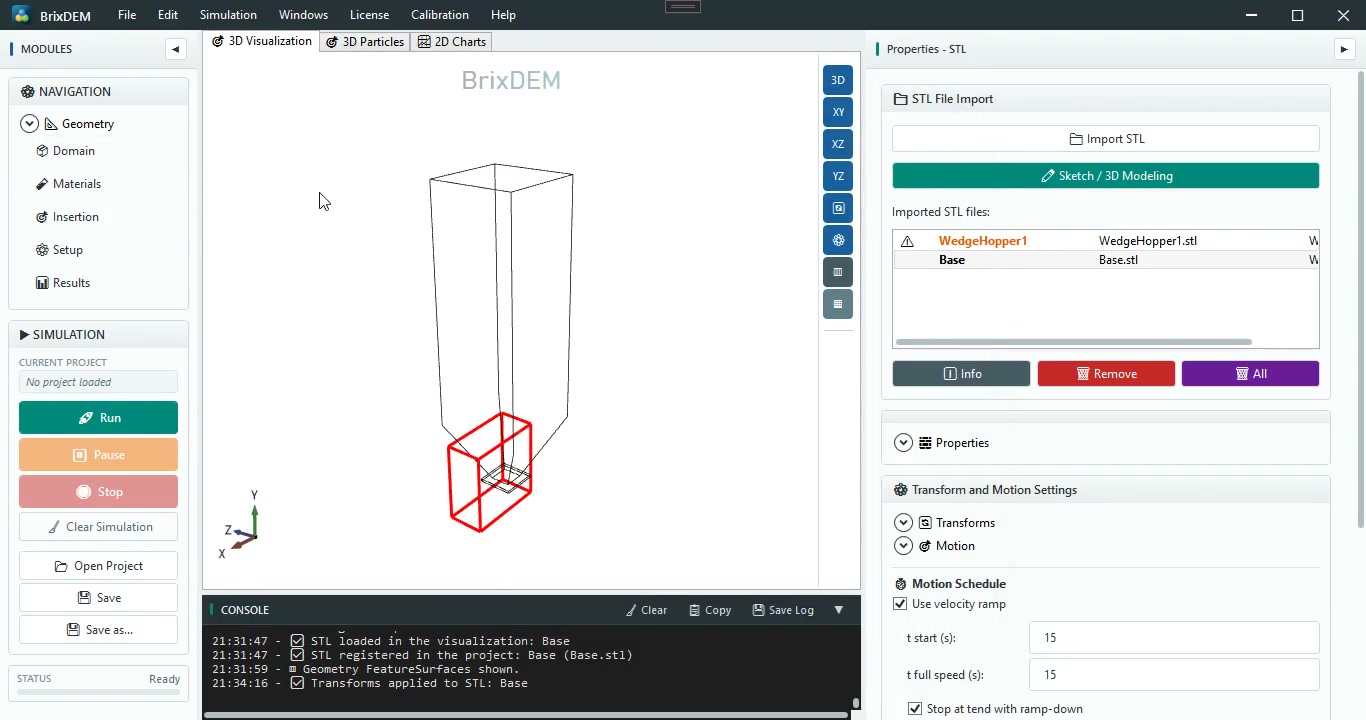
- Open a new project and, in Sketch Modeler, create a Wedge/Chisel Hopper. Use top length 0.250 m, top width 0.250 m, base/hopper height 1.400 m and total height to top 2.000 m. The properties of the solid used in this case show a 0.057 m × 0.057 m outlet.
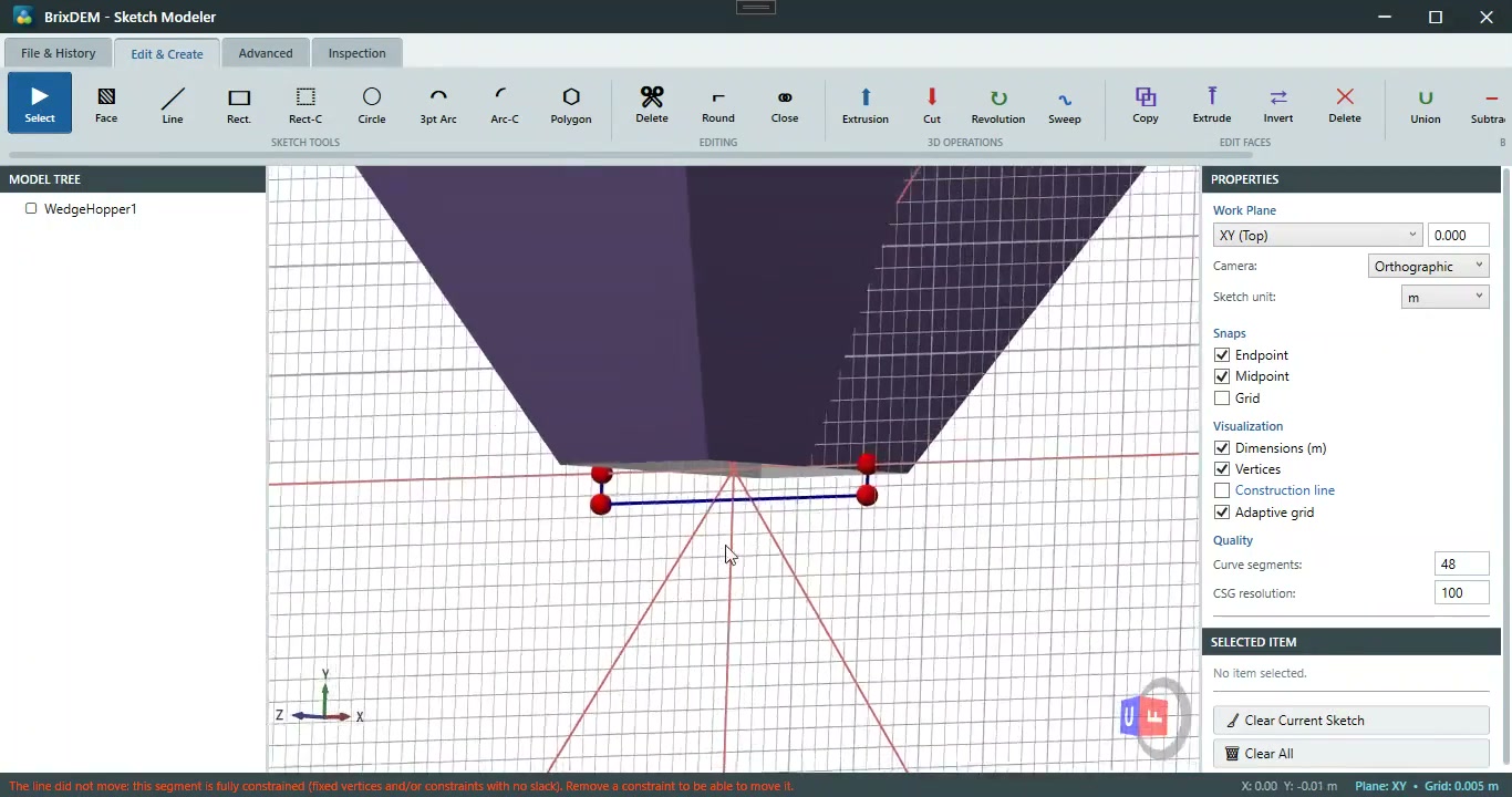
- At the lower opening, draw a rectangle centred on the outlet. Close the profile and use Extrude to make the plate: Symmetric direction, XY plane and final height 0.100 m. The plate is an extruded solid, not an unthickened sketch line.
- Export the silo and plate as separate STLs, keeping the same origin and scale.
25.2. Import the geometries
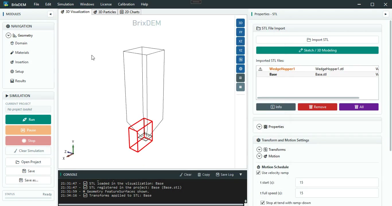
- Under Geometry › STL, import the silo STL and the plate STL. Keep both geometries fixed, with no prescribed motion.
- Check scale, position, faces and opening. The plate must be aligned below the outlet and must not close the silo interior.
25.3. Set the domain
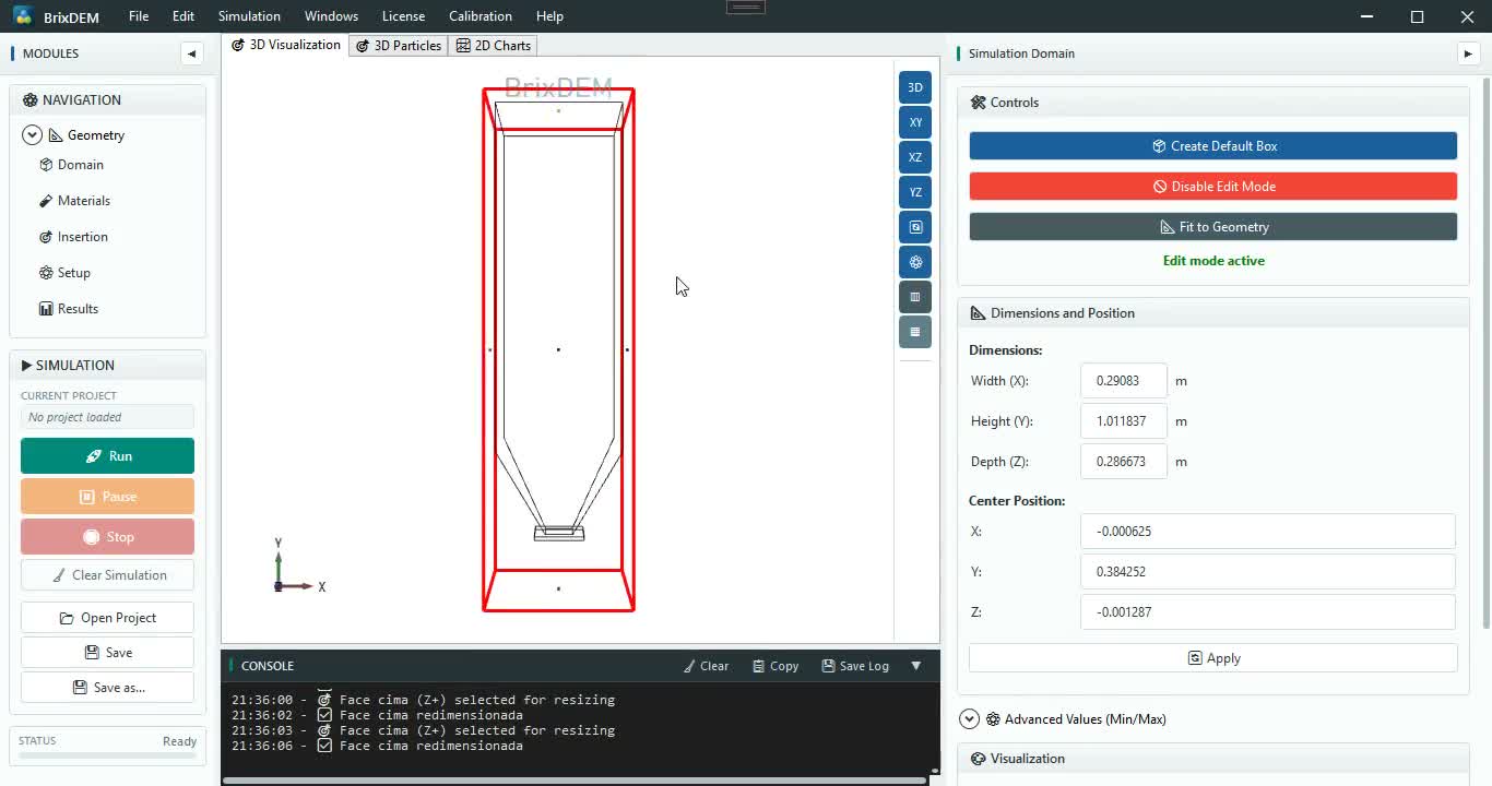
- Create a domain around the 0.250 m × 0.250 m × 2.000 m silo, the plate, the inlet and the space below the outlet.
- Leave margin in all directions so that particles are not created on a wall and particles removed by the outlet can leave the domain.
25.4. Materials and interactions
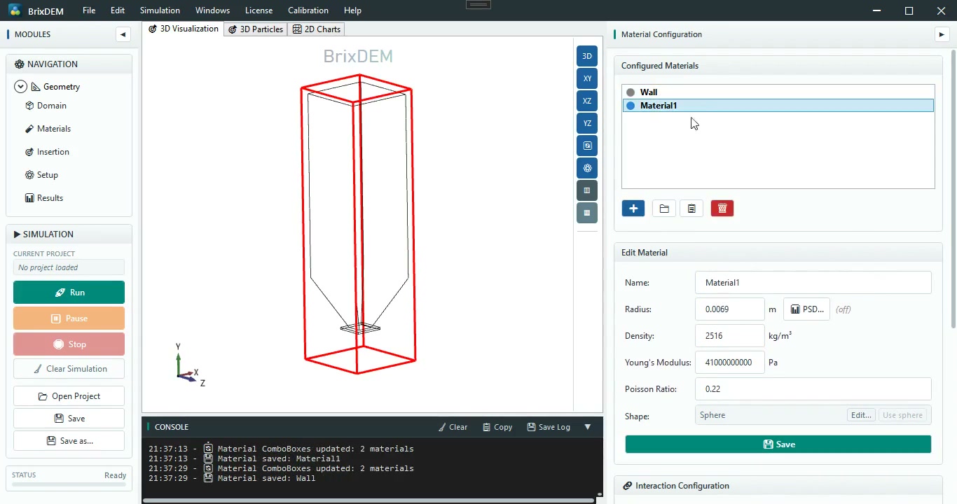
- Create particle material Material1: radius 0.0069 m, density 2516 kg/m³, Young’s modulus 410000000000 Pa and Poisson ratio 0.22.
- Create wall material Wall: radius 0.005 m, density 7800 kg/m³, Young’s modulus 410000000000 Pa and Poisson ratio 0.20.
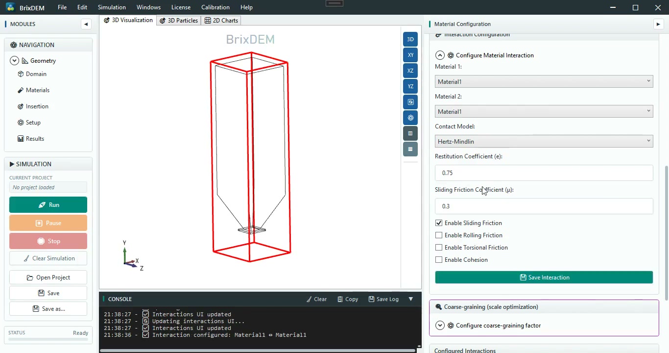
- For Material1–Material1 and Material1–Wall, choose Hertz–Mindlin, restitution e = 0.75 and sliding friction μ = 0.30. Leave rolling friction, torsional friction and cohesion disabled. Save each interaction.
25.5. Inlet and outlet
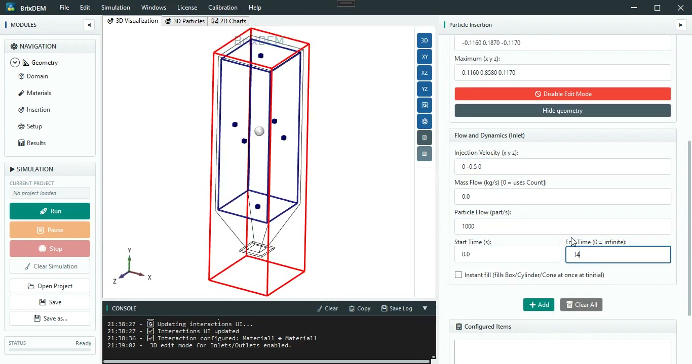
- Create a Box inlet with Material1. Use minimum (−0.1160; 0.1870; −0.1170) m and maximum (0.1160; 0.8580; 0.1170) m. Injection velocity is (0; −0.5; 0) m/s.
- Use a particle flow rate of 1000 part/s, mass flow 0, start 0 s, end 14 s, with Instant fill unchecked.
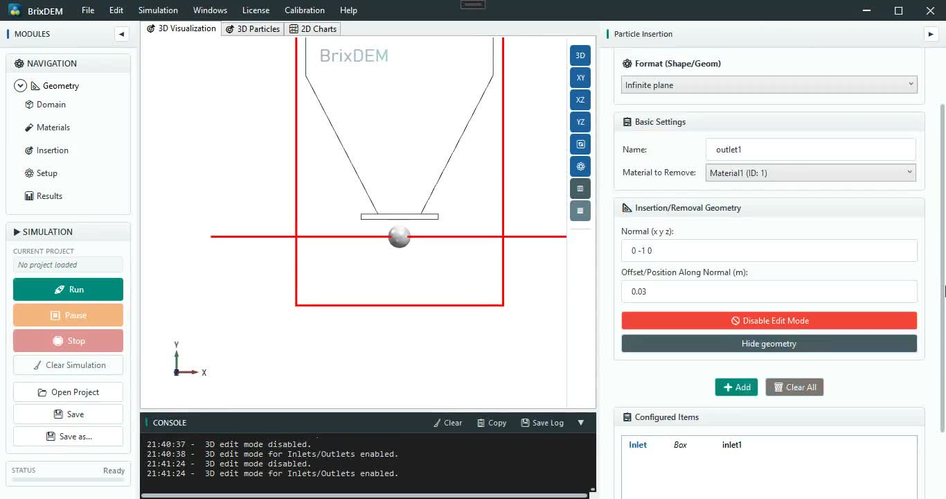
- Create outlet1 as an Infinite plane that removes Material1, with normal (0; −1; 0) and offset along the normal 0.03 m. Place it below the plate to record discharge.
25.6. Simulation setup
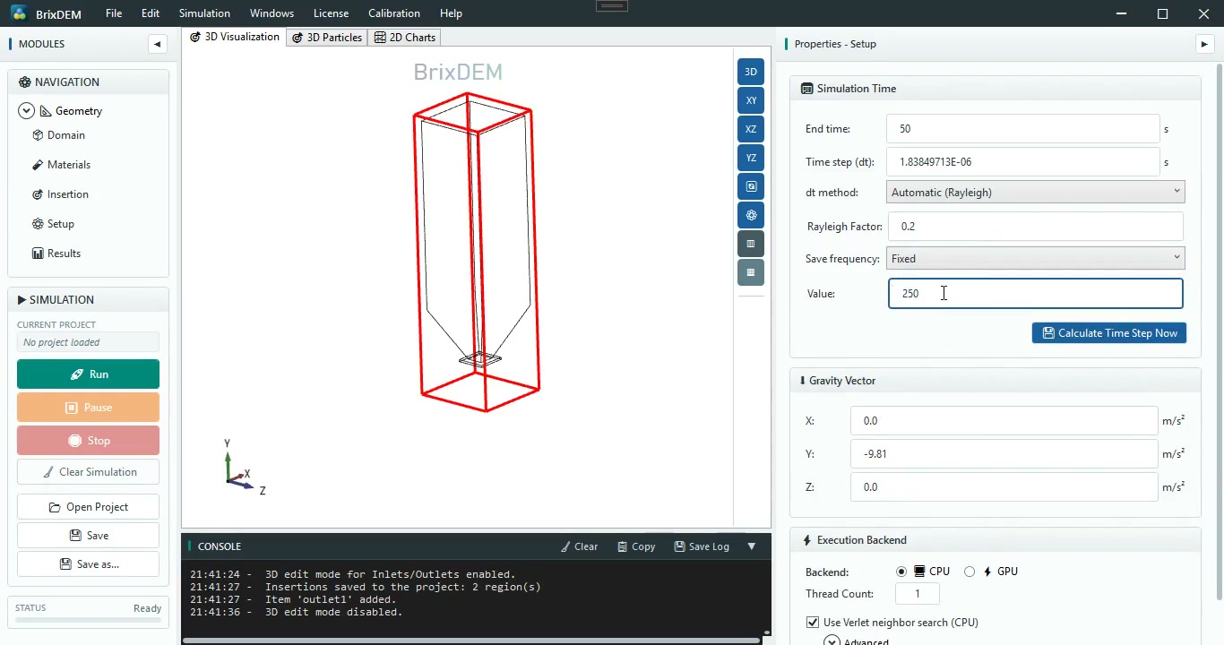
- Set end time 50 s, gravity (0; −9.81; 0) m/s², and Automatic (Rayleigh) time-step method with Rayleigh factor 0.2.
- Use the case time step: dt = 1.83849713 × 10⁻⁶ s. With Save frequency = Fixed, enter Save Count/Value = 250.
- Run on the CPU backend with Verlet neighbor search enabled. Save the project before starting.
25.7. Run and check the discharge
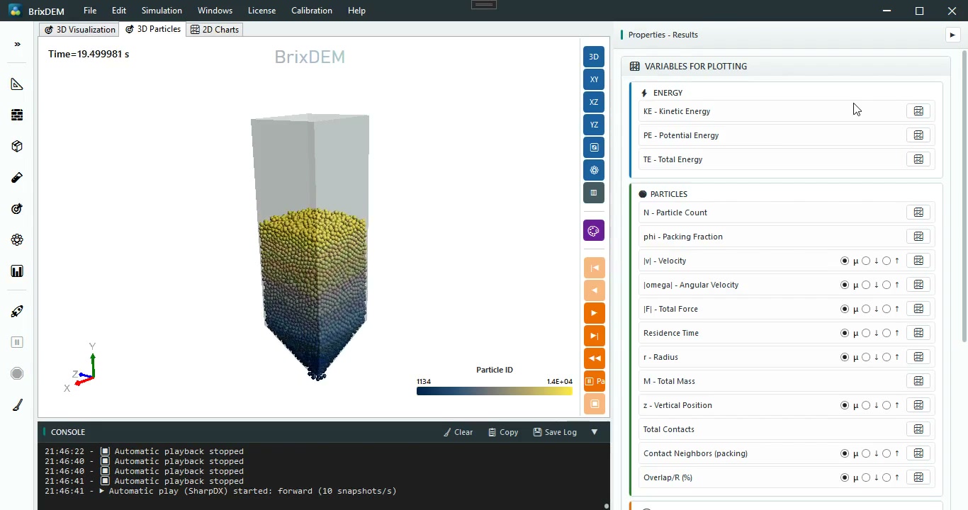
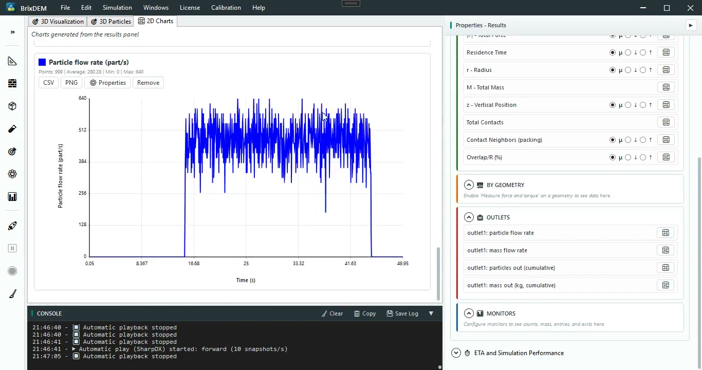
- Start the simulation and confirm that the inlet fills the body without explosive overlap, particles descend through the hopper, and outlet1 records removed particles.
- Check the results for discharge beginning near 14 s, particle count and removed mass. Compare the 3D view with the flow chart before changing any parameter.
Reproduction complete. If the result differs, first check STL scale/origin, Wedge Hopper dimensions, extruded plate thickness, inlet limits, outlet normal/offset, interactions, dt and Save Count.