
Sketch Modeler and 3D Modeling
Internal parametric CAD environment to create geometries without external tools, with industrial equipment library.
8.1 Open Sketch Modeler
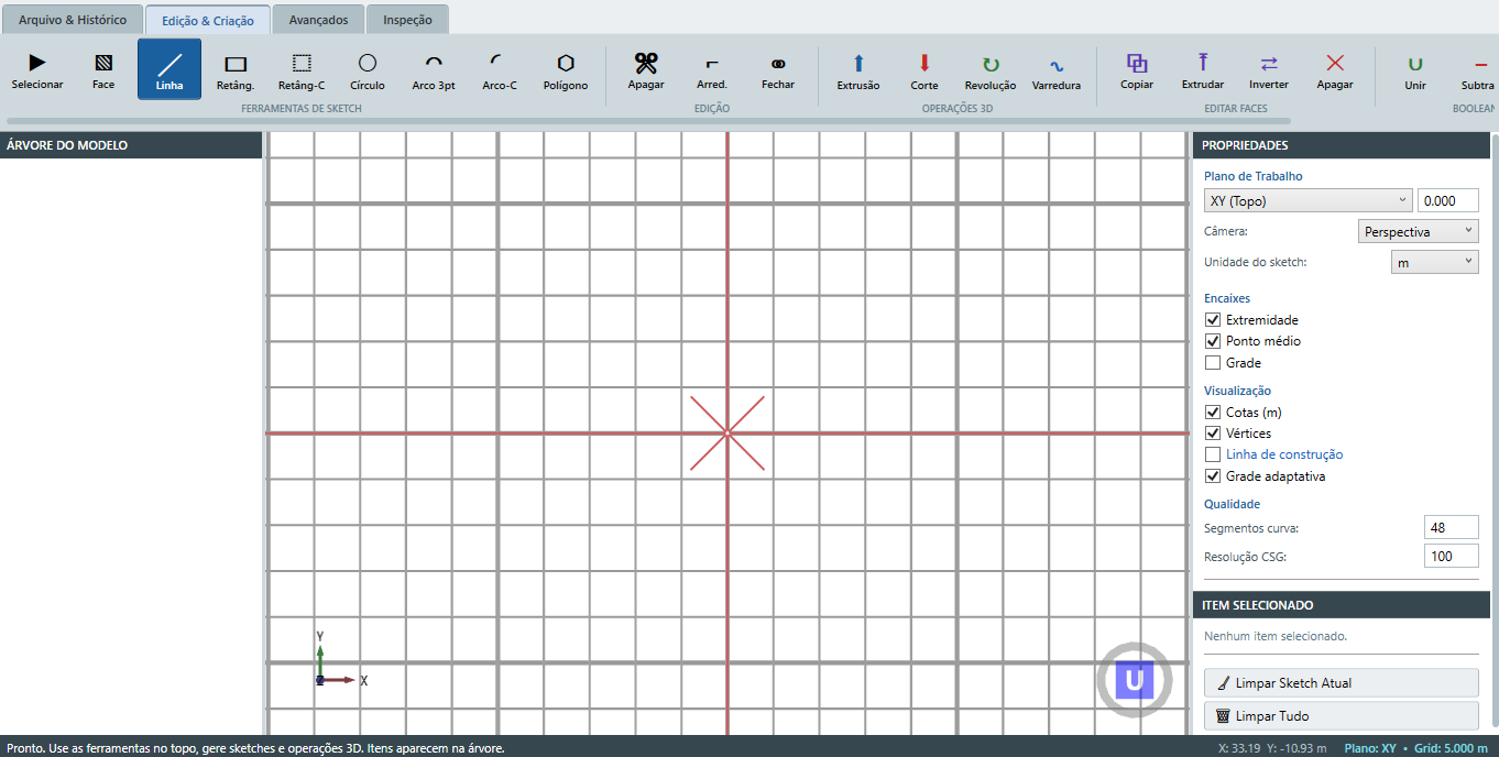
In the STL panel, click Sketch / 3D Modeling. Sketch Modeler opens in a separate window with tab bar at the top (File & History, Editing & Creation, Advanced), model tree to the left, drawing area to the center and property panel to the right. The sketch is oriented in Work plane (XY, YZ or ZX) and for a sketch unit (mm, cm or m).
8.2 File & History
The Tab File & History contains Save, Open, Undo, Redo, Export STL and Send to main window. Use Send when the geometry created must enter directly as STL into BrixDEM, without saving intermediate file.
8.3 Editing & Creation
The Tab Editing & Creation combines 2D drawing tools and solid operations:
- Sketch Tools: Select, Face, Line, Rectangle, Centered rectangle, Circle, Three-point arc, Centered arc, Polygon;
- Editing: Delete, Round (fillet), Close contour.

8.4 3D operations
From a closed sketch, Sketch Modeler applies solid operations:
| OPERATION | WHAT IT DOES |
|---|---|
| Extrusion | Linear extrusion of sketch along one direction |
| Cut | Extrusion subtraction (cut) |
| Revolution | Sketch rotation around an axis |
| Sweep | Sweep along a path |
| Union / Subtract / Intersection | Boolean operations between solids |
| Linear / circular pattern | Replication along a vector or around an axis |
8.5 Sketch Properties
The right panel controls the Work plane and the offset, the camera (perspective/orthographic), the sketch unit, snaps (endpoint, midpoint, grid), preview (dimensions, vertices, construction line, adaptive grid) and quality (segments per curve and CSG resolution of Boolean operations). Increasing quality improves curved surfaces at the cost of more triangles.
8.6 Library of industrial geometries (Advanced tab)
The Tab Advanced offers ready parametric geometries of industrial equipment. Each model opens a form with parameters (length, diameters, pitch, clearances, thicknesses) and generates the solid directly on the scene.
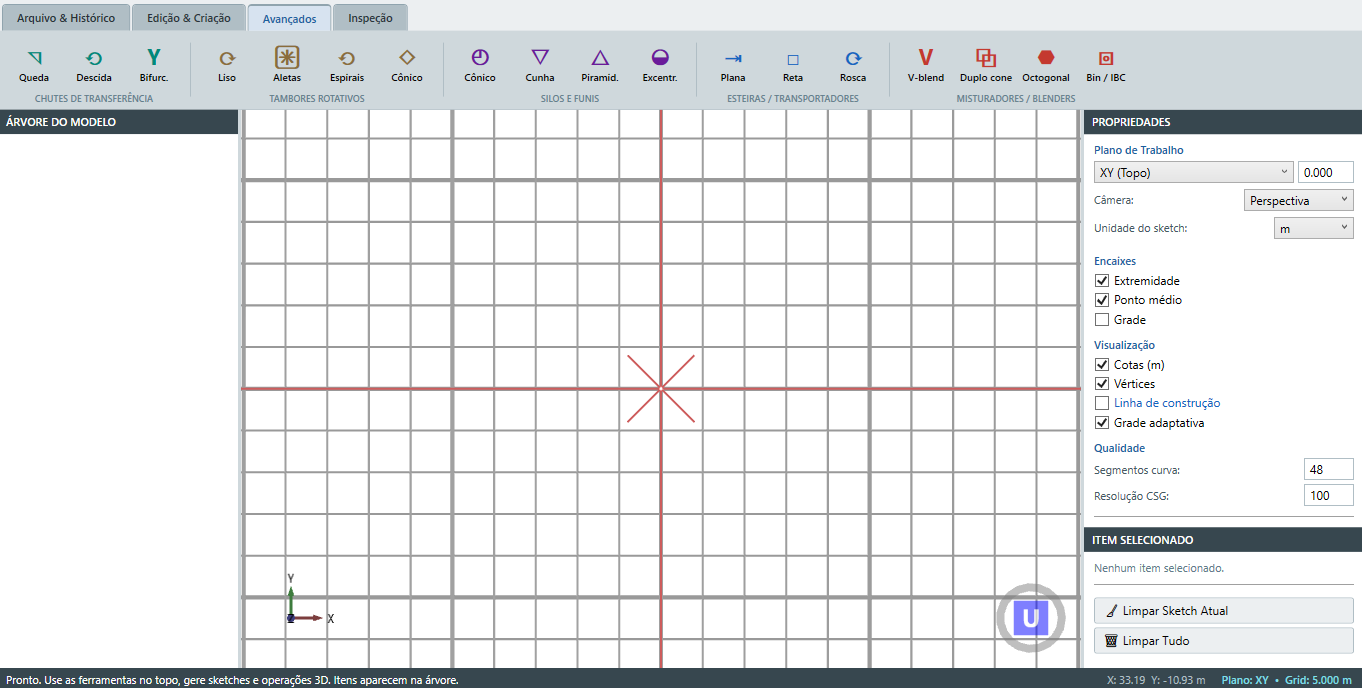

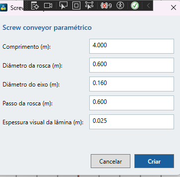
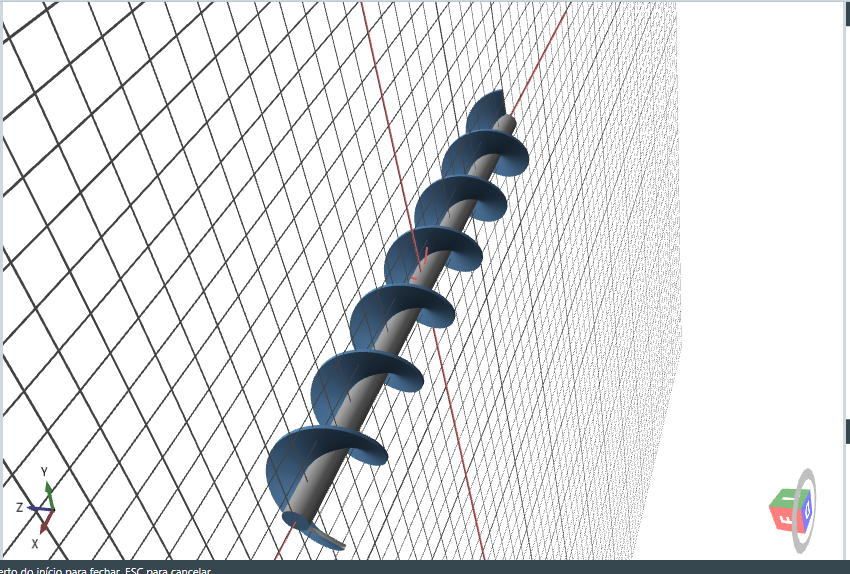
Each button opens one parametric form. For example, Helical conveyor (screw conveyor) asks length, screw diameter, shaft diameter, pitch and visual thickness of the blade; when confirming in Create, the solid is generated and added to the model tree.
Horizontal rotor mixers
Three horizontal-shaft mixers generate vessel and rotor in one step, as a closed assembly: the vessel comes out without gaps and the rotor arrives already positioned on the axis, ready to receive rotational motion (Chapter 7.5).
| MODEL | MAIN PARAMETERS |
|---|---|
| Ribbon | Vessel: length, width, U-bottom depth and straight wall above the U. Rotor: shaft diameter, outer and inner ribbon diameters, axial pitch, radial width and thickness of the ribbons, support stations and ribbon–vessel clearance |
| Paddle | Same U-shaped vessel. Rotor: shaft and outer diameters, number of stations, axial width / radial height / thickness of the paddle, attack angle and paddle–vessel clearance |
| Twin-shaft paddle | Two counter-rotating paddle rotors, with shaft spacing as an extra parameter; the vessel can be W-shaped |
8.7 CAD geometry import (STEP, IGES, OBJ, STL)
Besides drawing from scratch, Sketch Modeler imports ready-made geometry from the File & History tab. Accepted formats:
| FORMAT | WHAT IT IS | NOTE |
|---|---|---|
| STEP (.step, .stp) | Parametric CAD solid — the most complete/robust format for mechanical parts | Converted internally by a dedicated CAD converter |
| IGES (.igs, .iges) | CAD surfaces/solids, older format than STEP | Same conversion path as STEP |
| OBJ (.obj) | Triangle mesh (Wavefront) | Only the geometry is read: materials/textures (mtllib/usemtl), normals (vn) and groups/objects (g/o) in the file are ignored — everything collapses into a single mesh. Faces with more than 3 vertices are triangulated automatically |
| STL (.stl) | Triangle mesh already in the solver's native format | Direct import, no conversion |
Once imported, the geometry enters the model tree like any solid created in the Sketch — it can be repositioned, combined with boolean operations, or sent to BrixDEM through the same flow (8.2).
.brixsketch format (Save). There is no export to STEP/IGES/OBJ - to hand an edited part back to an external CAD, export STL and convert it there.