
The BrixDEM Interface
Main layout, panels, tabs and application shortcuts.
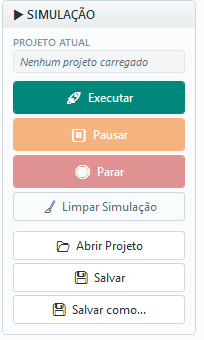
The main window organizes the workflow in four functional regions: a top bar with menus and simulation actions; the navigation panel on the left with the project modules; central area with display tabs and graphics; and property panel on the right. The lower console records solver activity. This organization allows all configuration and analysis to happen in a single window.
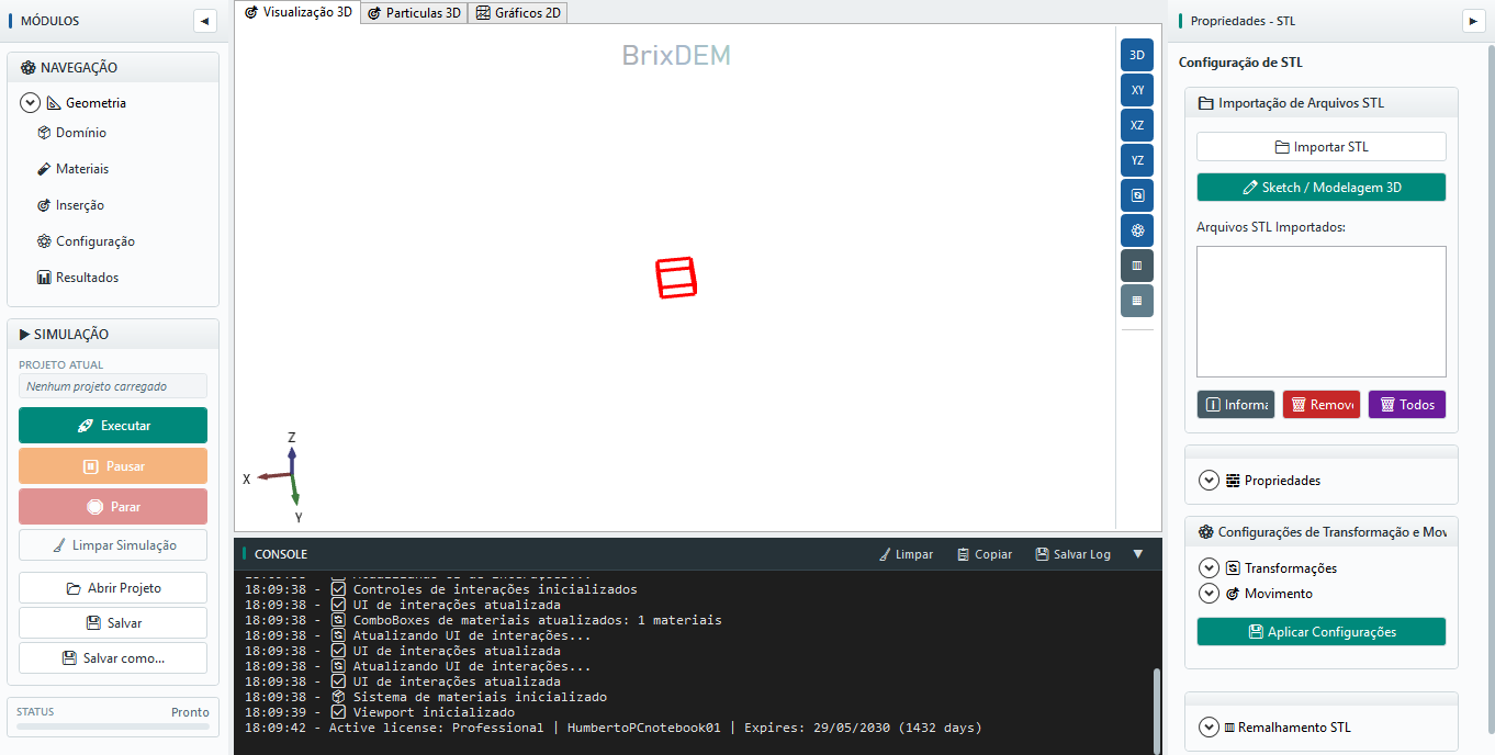
4.1 Menubar
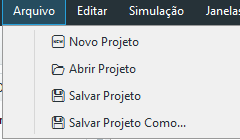
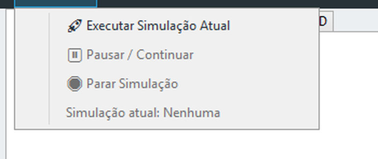
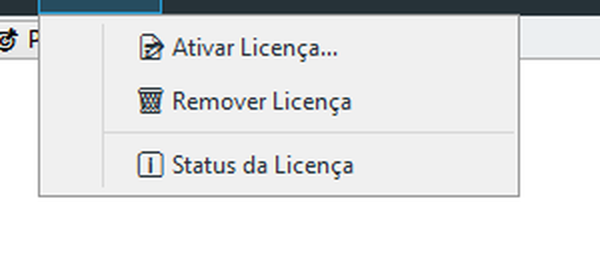
The top bar brings together six menus. The screenshots below show the contents of each.
| MENU | CONTENTS |
|---|---|
| File | New Project, Open, Save, Save As, Export/Import Complete Settings |
| Edit | Copy, Paste, Delete, Undo and Redo (with shortcuts) |
| Simulation | Run Current Simulation, Pause/Continue, Stop Simulation, active simulation status |
| Windows | Toggle Properties and Toggle Console |
| License | Activate License, Remove License and License Status |
| Calibration | Assistants: Particle drop, inclined plane (sliding/rolling), angle of repose (and cohesion), apparent density |
4.2 Navigation panel
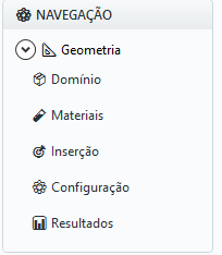
The left panel organizes the pre-processing flow as a tree. The node Geometry is expandable and contains the submodules STL and Surfaces:
- Geometry › STL - import external files;
- Geometry › Surfaces - create primitives (box, cylinder, plane);
- Domain - defining the computational region;
- Materials - to create materials and pairwise interactions;
- Insertion - configure inlets and outlets;
- Settings - numerical parameters (timestep, gravity, backend, parallelism);
- Results - select which variables to record and plot.
4.3 Property Panel
The right panel changes according to the selected module. It contains all editable parameters of the active item: STL, surfaces, materials, inlets/outlets, numerical setup, domain and results. The content is structured into collapsible expanders to reduce visual load.
4.4 Console
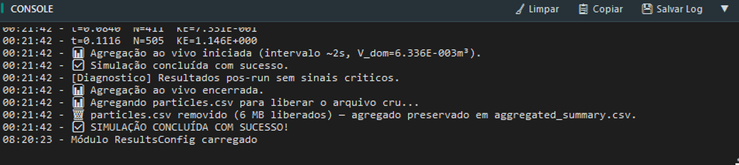
The lower console is the main source of diagnostic information during execution. It shows module loading, import events, solver startup/progress/completion, validation warnings and errors. The buttons Clear, Copy and Save Log allow capturing messages for technical reports.
4.5 Common Shortcuts
| SHORTCUT | ACTION |
|---|---|
| Ctrl + C / Ctrl + V | Copy / Paste |
| Del | Delete selected item |
| Ctrl + Z / Ctrl + Y | Undo / Redo |
Projects and shortcuts. Use Ctrl+N for New Project, Ctrl+O for Open and Ctrl+S for Save. The window title shows the open project and marks unsaved changes. Under File › Recent Projects, reopen a project; if it has moved or been deleted, the application reports the missing file and offers to remove its entry.
4.6 Interface size
Open Interface size in the top menu and choose a comfortable scale for the display. This changes control sizes, not the physical dimensions of the project; verify dimensions in Geometry and with the 3D ruler.