
Geometry: STL and Primitive Surfaces
Import, transformation, motion and remeshing of surfaces that interact with particles.
7.1 STL module
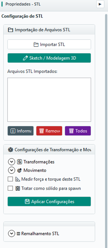
The module Geometry › STL allows you to import STL files, view the list of active geometries, remove items, consult mesh information, apply transformations, set motion and enable force/torque measurement per body. The panel is organized into: import and access to Sketch Modeler; list of imported STLs; transformation and movement settings; and remeshing.
7.2 Import STL
Click Import STL and select the file in the dialog. After import:
- Check the name in the list of imported STLs;
- Check the visual scale in viewport;
- assign material to the corresponding wall, where applicable;
- Use Information to review mesh data (no of triangles, size, scale, movement).
7.3 Remove STL
Use Remove to delete the selected item or All to clear the entire list. Removal also eliminates visualization and associated references (materials, motion, force measurement).
7.4 Transformations
The expander Transformations includes scale factor, translation X/Y/Z (in meters) and rotation X/Y/Z (in degrees). Use them to correct import scale, shift the origin and orient the geometry.
7.5 Surface movement
The expander Movement prescribes the kinematics of geometry - it moves in an imposed way (it is not dragged by particles), but transmits force and momentum to the particles it touches. Several types are available; what each parameter does is detailed below the table.
| TYPE | TYPICAL APPLICATION |
|---|---|
| Stationary | Fixed walls, bottom, container, gutters |
| Linear | Piston, pusher plate, feeder |
| Rotary | Drum, screw, paddles, agitator |
| Vibration | Vibrating sieve, densimetric table |
| Belt / Conveyor | Belt conveyor |
| Elevator | Bucket elevator (closed loop) |
| Free-body 6-DOF | Collection bucket, impact-actuated flap/door, force test rig — any part that must react to the physics instead of following a prescribed path (§7.11) |
The table below details exactly what to set up in each model - what each field means and the expected unit:
| MODEL | FIELD TO CONFIGURE | MEANING / UNIT |
|---|---|---|
| Stationary | - (none) | The geometry does not move; this is the default. |
| Linear | Velocity vector v (vx, v y, v z) | Direction and magnitude of translation [m/s]. For example: (0; −0.2; 0) moves down at 0.2 m/s. |
| Rotary | Vector ω (ωx, ω y, ω z) | Rotation axis (direction) and angular velocity (magnitude) [rad/s]. E.g. (0; 0; 2.09) ≈ 20 rpm in the XY plane. |
| Rotary | Centre of rotation (cx, c y, c z) | Point through which the spin axis passes [m]. Place on the actual axis of the drum. |
| Vibration | Amplitude A | Maximum displacement of oscillation [m]. |
| Vibration | Frequency f | Number of cycles per second [Hz]. |
| Vibration | Vibration direction | Vector that defines along which axis the surface oscillates. |
| Belt / Conveyor | Belt speed | Tangential speed of the mesh “skin” [m/s]; the geometry does not translate. |
| Elevator | Centre A and Centre B | The two drum centres (below and above) of the circuit [m]. |
| Elevator | Drum shaft | Vector of the axis around which the arcs are drawn. |
| Elevator | Radius | Radius of the semicircular arcs connecting the straight sections [m]. |
| Elevator | Track speed | Speed of the bucket along the closed circuit [m/s]. |
| Free-body 6-DOF | Mass, center of mass, inertia, initial velocities, axis locks, hinge | Full Newtonian dynamics (gravity + contact) — see 7.11 for the parameter list. |
7.6 Acceleration ramp
The ramp smooths the start and end of motion, avoiding the numerical shock that would occur if geometry jumped from rest to full velocity in a single step (this would launch particles in contact and destabilize the case). The speed increases linearly from rest to full value along the ascent ramp, is maintained during the regime and optionally decays at the end. The ramp and motion-segment parameters:
| PARAMETER | WHAT IT DOES |
|---|---|
| Start time (t0) | Time at which motion starts from rest. Before t₀, the geometry remains stationary. |
| Full speed time | Duration of the acceleration ramp, from t₀ to 100% of v/ω. A larger value gives a smoother start. |
| Stop at end time | If checked, motion decelerates and stops as the simulation end time approaches. |
| Duration of the descent ramp | Time to slow down from 100% until rest (when shutdown is active). |
7.7 Measurement of force and torque
Option Measure force and torque of this STL enables body outputs, recorded on results/.../body_forces.csv. Use to evaluate torque in rotating drums and mills, load in chutes and liners, force on silo and hopper walls, and time variation of loads in mechanical designs.
7.8 STL remeshing
The panel STL Remeshing adjusts the triangle density of the selected mesh. Increasing density subdivides triangles preserving shape; decreasing it returns to the original mesh or to a less dense version, avoiding destructive simplification.
| SITUATION | RECOMMENDATION |
|---|---|
| Very coarse mesh | Bad contact, particles can "jump" surfaces. Increase the density. |
| Very dense mesh | High computational cost without physical benefit. Reduce the density. |
| Curved surfaces | They need enough density to represent the curvature. |
| Details < particle radius | They don't usually justify the cost of keeping them on the mesh. |
7.9 Primitive surfaces
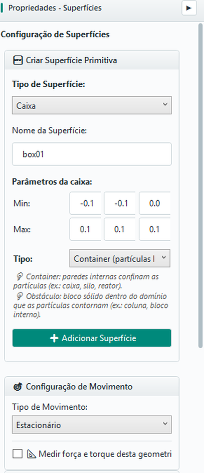
The module Geometry › Surfaces creates surfaces without need of STL file. Three types are available:
- Box - rectangular box defined by min/max; can be container (particles are inside) or obstacle (particles are outside);
- Cylinder - defined by two axis points, radius and optionally secondary radius (conical geometry) and lids;
- Plane - defined by point, normal and size; there are presets for floor, ceiling and side walls. Normal is critical: determines the side on which particles interact.
7.10 Assignment of material to surfaces
Each surface (STL or primitive) must have one wall material associated, which defines the side of the pairwise interaction. Typical wall materials: carbon steel, rubber, ceramic liner, concrete. The actual behavior of contact depends on interaction (pair particle material × wall material), not only of isolated materials - see Chapter 10.
7.11 Free-body 6-DOF (Newtonian dynamics)
Unlike the models above — which prescribe the trajectory (the body follows exactly the configured velocity/rotation, no matter what touches it) —, the Free-body 6-DOF mode lets the STL move under the simulation's own physics: gravity and the contact forces/torques received from the particles accelerate it, exactly as a large particle would respond. It is the right model for a part that must react to the material instead of following an imposed path — a collection bucket that swings when struck, a flap that opens under load, a float, or a test rig used to measure impact force. Available for STL only (not for primitive Box/Cylinder/Planee).
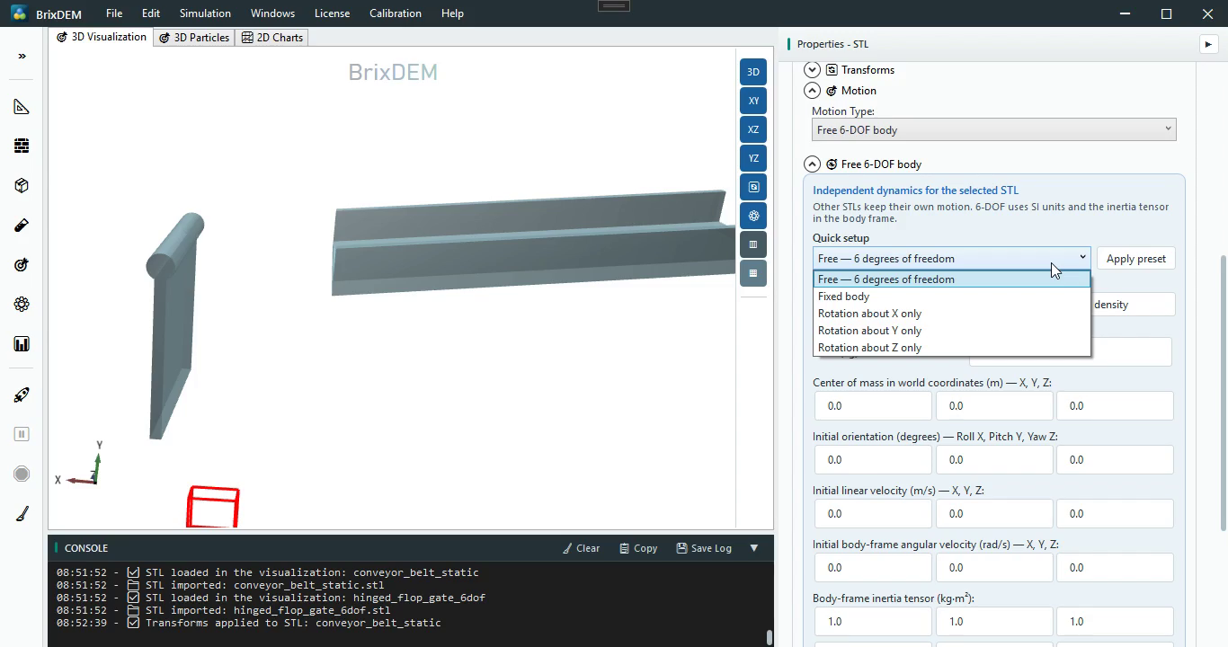
Select Free-body 6-DOF in the same Motion Type selector (7.5). Three presets speed up the initial setup:
- Free — 6 degrees of freedom — no axis locked; the body translates and rotates freely;
- Fixed body — every axis locked (equivalent to Stationary, but inside the 6-DOF flow — useful for testing the setup before releasing degrees of freedom);
- Rotation only around X/Y/Z — locks translation and the other two rotations, leaving the body free to spin about a single axis (e.g., a hinged door, a tipping gate).
For mass properties, Compute STL mass, center and inertia + material density automatically derives mass, center of mass, and the inertia tensor from mesh volume and material density. The mesh must be closed (watertight); for open meshes, repair the STL or enter values obtained from CAD/testing. Never copy mass or inertia from a different body.
| INTERFACE SECTION | WHAT IT DOES | HOW TO SET IT |
|---|---|---|
| Quick setup | Fills the six Tx, Ty, Tz, Rx, Ry, and Rz locks. | Select Free, Fixed, or rotation about X/Y/Z and click Apply preset. Then check the effective-DOF summary. |
| Mass | Sets resistance to linear acceleration [kg]. | Use automatic calculation with a closed STL and correct density; edit manually only from reliable data. |
| World center of mass | The X/Y/Z point [m] where translation is integrated and torque arms are measured. | Use the calculated value; after repositioning the STL, recalculate or update the world coordinates. |
| Initial orientation | Roll X, Pitch Y, and Yaw Z [degrees], converted to a quaternion. | Enter the actual initial pose. Avoid applying the same rotation in both the STL transform and these fields without checking the preview. |
| Initial linear velocity | World v₀ vector X/Y/Z [m/s]. | Leave zero to start from rest or enter the physical velocity at the initial instant. |
| Initial angular velocity | Body-frame ω₀ vector X/Y/Z [rad/s]. | Leave zero to start from rest. Convert rpm to rad/s when necessary. |
| Inertia tensor | Ixx, Iyy, Izz, Ixy, Ixz, and Iyz [kg·m²] in the body frame. | Prefer automatic calculation. The tensor must be symmetric and positive definite. |
| External force and torque | Add constant world vectors [N] and [N·m] on top of gravity and contacts. | Use zero when no known external load exists; do not use these fields to imitate a hinge. |
| Axis locks | Individually block Tx/Ty/Tz and Rx/Ry/Rz. | Check only the degrees that must remain immobile. For a physical joint, use Physical hinge. |
| Physical hinge | Fixes a world pivot and allows rotation only about the axis vector. | Enable it; enter a pivot X/Y/Z [m] on the real hinge line and a nonzero axis such as (0,0,1). |
| Hybrid drive | Controls linear or angular velocity with limited force/torque while other degrees remain dynamic. | Set axis, target, gain, and maximum limit. Start with a moderate gain and verify that the controller does not dominate contacts. |
| Springs and dampers | Create a linear reaction about a rest position and/or angular reaction about a target orientation. | Enable the group, copy the initial state as reference, and enter k and c by axis. Start conservatively and check stability. |
| Advanced elastic limits | Apply a penalty beyond minimum/maximum position [m] or relative rotation [rad]. | Enable by axis and enter min., max., k, and c. k=0 creates no reaction; slight overshoot is expected. |
7.11.1 Available free-body 6-DOF outputs
When the project contains at least one 6-DOF STL, the 6-DOF Bodies group appears in Results and reads free_body_dynamics.csv. The only quick series currently available are:
- Center-of-mass position — X, Y, and Z [m];
- Linear velocity — components and magnitude [m/s];
- Orientation (quaternion) — W, X, Y, and Z;
- Angular velocity — components and magnitude [rad/s];
- Resultant force — components and magnitude [N];
- Resultant torque — components and magnitude [N·m];
- Mechanical power — instantaneous power [W].
7.12 STL colors and opacity
Use the geometry color swatch and opacity control to organize the view. Color and transparency are visual properties saved in the project; they do not assign material, friction or boundary conditions. Check physical assignments in the materials/interactions list.